Solid Shell
🌐 KR
Description
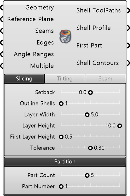
This is a component that generates shell deposition toolpaths from a closed solid geometry. It allows you to configure detailed settings such as the starting position, spacing, height, and tilting degree of the target planes. If the geometry is large, it can export the operation data by dividing it into partitions.
| Input
| Name | Type | Description |
|---|---|---|
| Geometry | Geometry | Target geometry for slicing. Input Brep or Mesh. |
| Reference Plane | Plane | Reference plane for slicing. Set identical to the build plate direction. Layers are generated along the Z-axis direction of the plane. Default: WorldXY. |
| Seams | Curve | Guide curve that determines the starting point (Seam) location of each layer’s outer path. The intersection between the curve and the outer path is set as the layer starting point. |
| Edges | Curve | Guide curve used to tilt target planes formed around the geometry’s edges along the tangent direction of the edges. |
| Angle Ranges | Number | Angle Ranges |
| Multiple | Number | Multiple |
| Required Parameter
| Name | Type | Description |
|---|---|---|
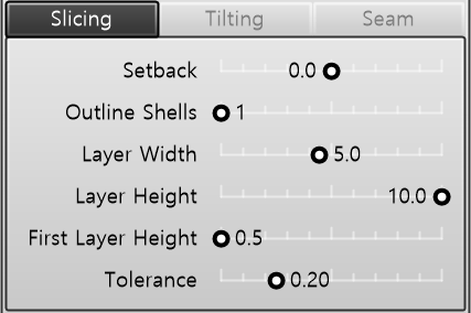
| Setback | Number | Inward/outward offset distance of the outer path based on the input geometry boundary (mm). |
| Outline Shells | Integer | Number of outer paths (shells) to be generated along the outline of the input geometry. |
| Layer Width | Number | Width of a single deposition path (bead width, mm). |
| Layer Height | Number | Height of a single deposition layer (layer thickness, mm). |
| First Layer Height | Number | Height of the first deposition layer in contact with the build plate (mm). |
| Tolerance | Number | Approximation tolerance for the path. |
| Name | Type | Description |
|---|---|---|
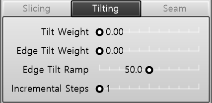
| Tilt Weight | Number | Weight to tilt the target Z-axis toward the surface inclination (overhang) direction in overhang geometries. Used to align the torch/extruder with the geometry's inclination. |
| Edge Tilt Weight | Number | Weight to tilt the target toward the tangent direction of the edge in geometries with edges. Edge reference curves use the component's Edges input. |
| Edge Tilt Ramp | Number | Distance to blend the Edge Tilt effect (mm). Gradually applies and releases Edge Tilt before and after the edge by this distance to mitigate path movement caused by abrupt edge tangent transitions. |
| Incremental Tilt Steps | Number | Number of layers (N) to gradually reach the configured Tilt Weight. Applies tilting step-by-step starting from initial layers near the build plate, preventing collisions and excessive robot movement caused by abrupt tilting in initial layers. |
| Name | Type | Description |
|---|---|---|
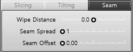
| Wipe Distance | Number | Nozzle wiping distance. • Positive (+): Proceeds with an overlapping path by this additional distance from the starting point after completing the outer path. • Negative (-): Terminates early before this distance from the end point of the outer path. |
| Seam Spread | Number | Distributes the seam starting points across N cycles to prevent seams from concentrating at a single location. Shifts path parameters by 1/N per layer and returns to the original position every N layers. • Example: N = 4 → Layer 1 = 0.0, Layer 2 = 0.25, Layer 3 = 0.75, Layer 4 = 0.0 (repeating). |
| Seam Offset | Integer | Offset to collectively adjust the seam positions of all layers. Uniformly shifts the entire sequence while maintaining the positional relationships between layers established by Seam Spread. |
| Name | Type | Description |
|---|---|---|
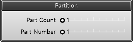
| Part Count | Integer | Number of parts to divide and slice the model into. • 1: Slices the entire model. / • N: Divides the model into N parts for partial slicing. |
| Part Number | Number | Part number (1 to N) to be sliced among the N divided parts. |
| Output
| Name | Type | Description |
|---|---|---|
| Shell ToolPaths | Shell ToolPaths | Generated deposition path data. |
| Shell Profile | Shell Profile | Reference profile information of the generated outer deposition path. |
| First Part | Boolean | Flag indicating whether the current Deposition ToolPath is the bottom-most (first) part. |
| Shell Contours | Curve | Polylines connecting the generated outer deposition paths. |