ParallelFinishing
🌐 KR
Description
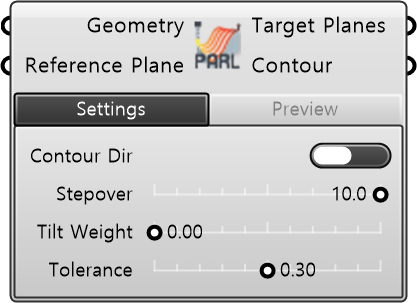
This is a component that generates a finishing toolpath along unidirectional parallel contour curves. Users can configure detailed settings such as the distance between target planes, layer-to-layer spacing, and tilting to suit the workpiece geometry.
| Input
| Name | Type | Description |
|---|---|---|
| Geometry | Geometry | Brep or Mesh geometry to be finish-machined. |
| Reference Plane | Plane | Reference plane for finishing path generation. |
| Required Parameter
| Name | Type | Description |
|---|---|---|
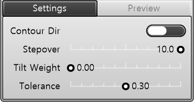
| Contour Direction | Toggle | Toggles parallel contour direction. • TRUE: X direction (Rotated by 90°). • FALSE: Reference Plane +Y direction (Default). |
| Stepover | Number | Distance between adjacent cutting paths (mm). |
| Tilt Weight | Number | Controls the degree to which the TCP tilts along the geometry surface normal, making the endmill perpendicular to the surface (0.0 = Reference Plane Z, 1.0 = Surface Normal). |
| Tolerance | Number | Approximation tolerance for the path. |
| Name | Type | Description |
|---|---|---|
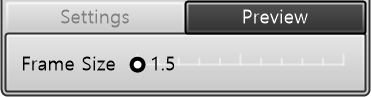
| Frame Size | Number | Frame size. |
| Output
| Name | Type | Description |
|---|---|---|
| Target Planes | Plane | Target planes of the generated hot-wire cutting path. |
| Contour | Curve | Polyline pattern connecting the generated finishing paths. |