FlyByCustom
🌐 KR
Description
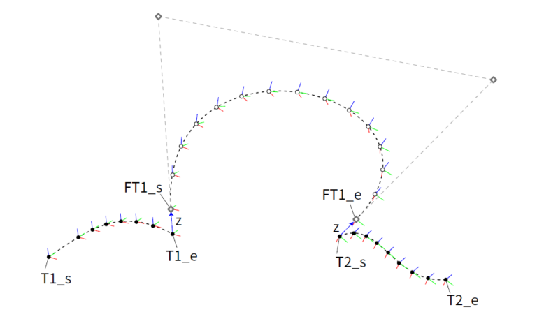
- This component generates new movement paths that pass between each branch of the input Robot TCP main path (Target Plane Input) DataTree. The FlyBy component essentially uses the last Plane of the current main path Branch[i] and the first Plane of the adjacent main path Branch[i+1] in the input to define new FlyBy Target Planes at a distance specified by the user.
Input
- TargetPlanes [Plane/DataTree]: Input the Target Planes corresponding to the TCP main path for applying FlyBy Targets.
- Approaching Dir. : Define the direction of entry for the generated movement paths.
- Leaving Dir. : Define the direction of exit for the generated movement paths.
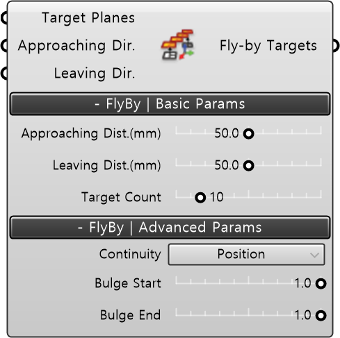
Built in param | Basic Params
- Approaching Dist. (mm): Determines the distance (in millimeters) to offset the last FlyBy Plane just before entering the main path. This distance defines how far the FlyBy Plane is displaced before entering the main path.
- Leaving Dist. (mm): Determines the distance (in millimeters) to offset the first FlyBy Plane just after leaving the main path. This distance defines how far the FlyBy Plane is displaced after leaving the main path.
- Target Count: Input the total number of FlyBy Planes to construct the movement paths (FlyBy ToolPath) between the main paths.
Built in param | Advanced Params
Advanced Param is an option that determines the profile of the movement path. The profile of the movement path is defined based on the conditions selected by the user in Builtin Param: Basic. This profile blends the direction vectors in which the first and last FlyBy Planes deviate from the main path.
- Continuity : Depending on the selected continuity condition, ensure that the origins of the generated FlyBy Planes lie on a linear or nonlinear curve. Default: Position (G0).
Continuity Description Reference: Rhinoceros Help - Continuity Description / Rhino 3D Modeling.
| Type | Description |
|---|---|
| Position(G0) | The profile of the movement path adopts a Blend Curve with Position (G0) continuity, aligning only the positions of the first and last Plane origins of the movement path. |
| Tangency(G1) | The profile of the movement path adopts a Blend Curve with Tangency (G1) continuity, aligning the positions of the first and last Plane origins of the movement path along with tangents in the direction vectors offset from those positions. |
| Curvature(G2) | The profile of the movement path adopts a Blend Curve with Curvature (G2) continuity, aligning the positions of the first and last Plane origins of the movement path along with tangents in the direction vectors offset from those positions and having the same radius of curvature. |

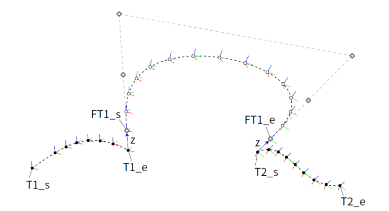
- Bulge Start : (For Tangency/Curvature conditions) Enter a value between 0 and 1 to edit the shape of the starting part of the movement path profile while maintaining continuity.
- Bulge End : (For Tangency/Curvature conditions) Enter a value between 0 and 1 to edit the shape of the ending part of the movement path profile while maintaining continuity.
Output
- Fly-by Targets : Based on the input conditions, output the generated movement paths in DataTree format. The FlyBy Targets Output includes FlyBy Planes corresponding to the initial entry and final exit from the main path, resulting in one more Branch than the number of Branches in the Target Planes Input. After assigning movement path instructions, the DataTree will consist of Paths starting with even indices [0], [2], [4], etc., facilitating easy merging of instructions and data for the main path.