Slicer Shell for Surface
🌐 KR
Description
- Custom Component for Generating Toolpaths for Open-Ended Planar Objects.
- This component assists in creating customized toolpaths for open-ended planar objects. Users can configure the spacing, height, and angles of the toolpath planes (Plane) according to their specific requirements.
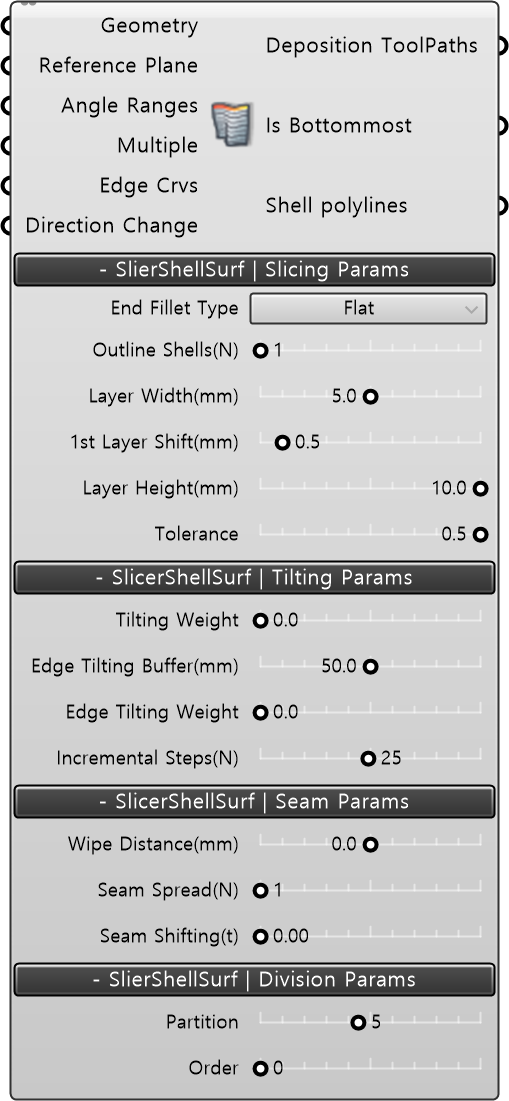
Input
- Geometry [Geometry] : Input the geometry modeling.
- Reference Plane [Plane] : Redefine and input the base plane of the modeling. Defaults to World XY.
Built-in Param | Slicing Params
- End Fillet Type: There are options for Flat/Round. When expanding the options for outlineShell, choose between Flat or Round for the finishing type of the stacked plane. The default value is Flat.
- Outline Shells(N) : Adds outline shell layers offsetting outside the main path. (N: integer value)
- Layer Wideth(mm) : Defines the distance between added outline shell layers.
- 1st layer Shift(mm) : Redefines the position of the first main path layer by shifting it upwards.
- Layer Height(mm) : Redefines the height between main path layers.
- Tolerance : Redefines the spacing between TargetPlanes within the main path.
- Tilting Weight : Redefines the inclination of the NormalVector to be between the normal vector of the layer modeling and the value between worldXY.
Built-in Param | Seam Params
- Wipe Distance(mm) : Extends the output length to match the existing main path according to the condition of 3DP materials.
- Seam Shifting(t) : Allows shifting the starting and ending points of the output within the position range of the main path.
Built-in Param | Division Params
- Partition : Divides the main path of the modeling into integer values for display.
- Order : Retrieves the index value of the divided partition for display.
Output
- Deposition ToolPaths : 적층 ToolPath Data를 출력한다.
- Is Bottommost : 모델링 제일 밑바닥면이 Closed되어있는지 체크한다. (null이 아닐 경우 True)
- Shell polylines : 모델링의 각 Layer의 ShellData를 polyline으로 출력한다.