Slicer Shell for Solid
🌐 KR
Description
- This component assists in creating custom toolpaths for closed curve objects. Users can customize the spacing, height, and angle of the tool path planes (Plane), allowing them to create paths tailored to their specific environments.
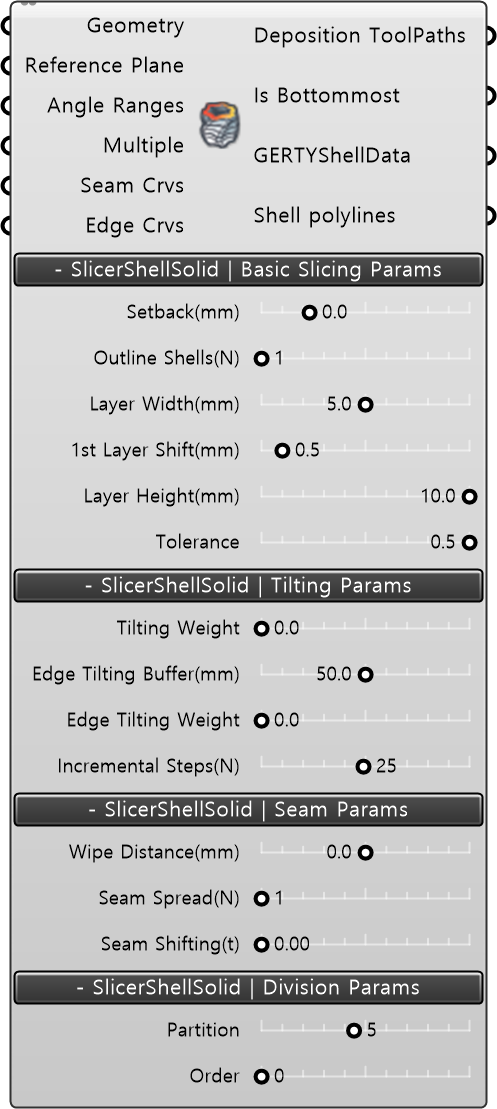
Input
- Geometry [Geometry] : Input the geometry modeling.
- Reference Plane [Plane] : Redefine and input the base plane of the modeling. By default, it accepts World XY.
Built-in Param | Basic Slicing Params
- Stepback(mm) : Redefines the main path by offsetting the outline of the main path modeling.
- Outline Shells(N) : Adds main path shell layers offset inward from the main path modeling. (N: integer value)
- Layer Wideth(mm) : Defines the distance between the added outline shell layers.
- 1st layer Shift(mm) : Moves the first main path layer upward (Shift).
- Layer Height(mm) : Redefines the height between main path layers.
- Tolerance : Redefines the spacing between TargetPlanes within the main path.
- Tilting Weight : Redefines the slope of the NormalVector between the normal vector of the layer modeling and World XY values.
Built-in Param | Seam Params
- Wipe Distance(mm) : Extends the output length to match the existing main path according to the condition of the 3DP material.
- Seam Spread(N) : Defines the start and end points of the output differently for each layer.
- Seam Shifting(t) : Allows shifting the start and end points of the output within the positions of the main path.
Built-in Param | Division Params
- Partition: Divides the main path of the output model into equal segments based on an integer value.
- Order : Displays the index values of the divided partitions.
Output
- Deposition ToolPaths: Outputs the layer-by-layer ToolPath data for additive manufacturing.
- Is Bottommost: Checks if the bottommost face of the model is closed. Returns True if it is not null.
- GertyShellData: Extracts the ShellData for each layer of the model.
- Shell polylines: Outputs the ShellData for each layer of the model as polylines.